Network Address Translation(NAT) and Port Address Translation(PAT) September 26, 2008
Posted by Ravindu Jayalath in Technical.add a comment
Here again we are going to discuss about another importanat topic in networking. We have mainly 3 types of NATTING. They are Static ,Dynamic and NAT overloading usually known as PAT. I will give you some basic examples why we need this concept. Let’s say that you have one public IP given by the ISP and you need to connect 20 PCs to the internet. There you can use this technique. Another example is you have a PC with IP 172.16.5.1 and you need to connect one of your application in that machine to another server in another network.But that netwoks firewall allowes only source IP 10.10.10.1 only to access that server. In that case you can NAT IP 172.16.5.1 in to 10.10.10.1 where you can access that server now.
Let’s define NAT terms:
• Inside local address – The IP address assigned to a host on the inside network. The address is usually not an IP address assigned by the Internet Network Information Center (InterNIC) or service provider. This address is likely to be an RFC 1918 private address.
• Inside global address – A legitimate IP address assigned by the InterNIC or service provider that represents one or more inside local IP addresses to the outside world.
• Outside local address – The IP address of an outside host as it is known to the hosts on the inside network.
• Outside global address – The IP address assigned to a host on the outside network. The owner of the host assigns this address.
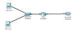
Let’s configure a static NAT between the private IP 10.6.1.2 & the public 171.69.68.10
Router(config)#ip nat inside source static 10.6.1.2 171.69.68.10
Router(config)#int e0
Router(config-if)#ip nat inside
Router(config-if)#int e1
Router(config-if)#ip nat outside
To configure dynamic inside source address translation an access list must permit only those addresses that are to be translated. Remember that there is an implicit “deny all” at the end of each access list.
Now lets NAT 2 PCs 10.1.1.1 and 10.1.1.2 in to public IP 194.16.10.1.If you have many public IPs you can use all in the pool as I used only one here.
Router(config)#ip nat pool Ravindu 194.16.10.1 194.16.10.1 netmask 255.255.255
Router(config)#access-list 7 permit 10.1.1.0 0.0.0.3
Router(config)#ip nat inside sourse list 7 pool Ravindu
Router(config)#int e0
Router(config-if)#ip nat inside
Router(config-if)#int s0
Router(config-if)#ip nat outside
–-Hope this has been useful for you and thank you for veiwing–
Design of a simple VLAN September 1, 2008
Posted by Ravindu Jayalath in Technical.add a comment
 VLAN are very important in case of limiting broadcast traffic and security and so on. So it is very important to learn how to configure a VLAN. Here are basic steps to da that.
According to the diagram fastethernet0/1 and fastethernet0/24 of switch 0 and fastethernet0/1 of switch 1 are trunk ports as every VLAN traffic goes through that ports.
Then fastethernet0/2 and fastethernet0/3 of Switch 0 and fastethernet0/2 and fastethernet0/3 of switch 1 are access links as they are conneted to particular VLANs.
Then here we have two switches. So we have to define Vlan Trunking Protocol to send VLAN information of one switch to other. There both switches should be in the same VTP domain and one Shoul be VTP Server.
When we create VLANs first we need to create and then we need to name the VLAN.
Now lets consider the step by step configurations.
Switch 0:
interface FastEthernet0/1
switchport mode trunk
interface FastEthernet0/24
switchport mode trunk
Switch 1:
interface FastEthernet0/1
switchport mode trunk
Trunking is done. Next we define the Vlan Trunking Protocol(VTP).
Switch 0:
vtp mode server
vtp domain MYVLAN
Switch 1:
vtp mode client
vtp domain MYVLAN
Now we will create VLANs.As we define VTP we need to do this in server switch only.
Switch 0:
vlan 2
name VLAN2
vlan 3
name VLAN3
Then we have to assign particular switch port to the appropriate VLAN.
Switch 0:
int fa0/2
switchport access vlan 2
int fa0/3
switchport access vlan 3
Switch 1:
int fa0/2
switchport access vlan 3
int fa0/3
switchport access vlan 2
Now everything is done. We can confirm it as shown below.
Switch#show vtp status
VTP Version : 2
Configuration Revision : 4
Maximum VLANs supported locally : 64
Number of existing VLANs : 7
VTP Operating Mode : Server
VTP Domain Name : MYVLAN
VTP Pruning Mode : Disabled
VTP V2 Mode : Disabled
VTP Traps Generation : Disabled
MD5 digest : 0x44 0xD9 0x26 0x26 0xB2 0x45 0xC0 0xBF
Configuration last modified by 0.0.0.0 at 3-1-93 00:30:27
Local updater ID is 0.0.0.0 (no valid interface found)
Switch#show vlan brief
VLAN Name Status Ports
—- ——————————– ——— ——————————-
1 default active Fa0/4, Fa0/5, Fa0/6, Fa0/7
Fa0/8, Fa0/9, Fa0/10, Fa0/11
Fa0/12, Fa0/13, Fa0/14, Fa0/15
Fa0/16, Fa0/17, Fa0/18, Fa0/19
Fa0/20, Fa0/21, Fa0/22, Fa0/23
2 VLAN2 active Fa0/2
3 VLAN3 active Fa0/3
1002 fddi-default active
1003 token-ring-default active
1004 fddinet-default active
1005 trnet-default active
Yo! man you are done with VLANs. Have fun
