Digitization in a nutshell October 12, 2017
Posted by Ravindu Jayalath in Uncategorized.add a comment
Be it banking & finance or telecommunication or any other industry, process automation, data digitization, customer convenience, green IT, so on and so forth are the most common terms that we hear nowadays with respect to the digitization. Since I’m more interested in to banking industry these days, there people talk about driving towards a cashless society with the introduction & improvements of digital based payment channels starting from basic credit cards to virtual wallets. This has become a more reality due to the introduction of third party payment methods such as mobile cash (mphesa, easy cash), QR code or URL based payments (PayPal Me, Google) and so on. Automated banking consists of basic ATM, Cash deposit machines to voice recognition kiosk based automated agent banking solutions are being introduced to avoid longs customer waiting queues in the branches.
What are the other new technological trends which have been opened in the industry with digitization? When more and more channels are opened to external parties, it also opened more and more vulnerabilities & backdoors. As a result many security concerns arise and many technological trends are being developed to mitigate them. People started thinking about advanced end point protection technologies, behavioral analysis based zero day attack protection solutions, DDoS attack mitigation technologies, SAPM filtering, vulnerability assessments, penetration testing, application specific firewalls such as WAF or DAF, one time password via SMS or tokens, dynamic CVV, etc. So I would say that it has been a win-win situation for many solution providers in the industry.
What are the advantages organizations get over digitization? Is it only customer convenience, carbon foot print reduction aka green IT or human resource reduction? We are living in era where data or information has more value than anything else. The one of the great advantage which people have not realized is how they can use the data which are collected through the digital channels can be analyzed & use them to improve the business opportunities. Big Data Analytics can be used to segment customers, identify their needs & market them the right product at right time. How Target Market Figured out a Teen Girl Was Pregnant before Her Father Did by identifying her web browsing patterns had been common example to know the power of analytics. Similarly when we browse some hotels or any other thing via Google we get similar kind of suggestions frequently is another example how the data analytics are built in to systems. Same trend can be implemented in banking also to target customer for various promotions for the data which are being collected via the digital channels. Same way we can offer them products via the same channels as well. Very simple example is offering a personnel loan to a target customer via simple ATM machine once he are accessing. This can be one of the greatest advantage which organization can take to target its consumers.
Global Server Load Balancing (GSLB) February 19, 2010
Posted by Ravindu Jayalath in Technical.1 comment so far
There are two well known methods of GSLB called,
- DNS based Global Server Load Balancing
- BGP Host Route Injection
The most common and one most common method would be the 1st one which is DNS based Global Server Load Balancing. GSLB directs DNS requests to the best-performing GSLB site in a distributed Internet environment and enables distribution of traffic across multiple sites, manages disaster recovery, and ensures that applications are consistently accessible. When a client sends a DNS request, the system determines the best-performing site and returns its IP to the client. Following features are some of features available in this load balancing technique.
- Directs client requests to the geographically closest GSLB site (geographic and network proximity-based traffic redirection)
- Directs client requests to surviving data centers when an outage occurs
- Directs client requests to alternate data centers, when a pre-defined traffic load limit is reached
- Directs client requests to be distributed among multiple data centers
According to above features, load balancing requirements, which users can be directed based on the users network address and failover between sites can be achieved.
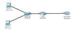
Sample Example is shown below. In this case simple failover and load balancing is demonstrated. To achieve more features like route traffic according to source network address, device would be configured with features such as proximity-based traffic redirection and so on.

Fig 01: Example of two sites and users connecting via Internet
Site A in has a virtual IP address (VIP) of 1.1.1.1, and Site B has a VIP of 2.2.2.2. A GSLB device is acting as the authoritative name server for www.mydomain.net. Upon a DNS query for www.mydomain.net, the job of the GSLB is to determine whether to return the IP address 1.1.1.1 or 2.2.2.2.
1. The stub resolver (a software program running on the client computer) makes a request to the assigned local DNS server.
2. The client’s DNS server performs an iterative resolution on behalf of the client, querying the root name servers and eventually ending up at the authoritative name server for www.mydomain.net. In this case the GSLB device is that authoritative name server.
3. The GSLB device performs some sort of communications with devices at each site, gathering information such as site health, number of connections, and response time.
4. Using the information gathered the GSLB device makes a determination as to the preferred site, and returns the answer to the client’s DNS server. The answer is either IP address 1.1.1.1 or IP address 2.2.2.2.
5. The DNS answer is returned to the client’s stub resolver.
6. After DNS resolution is complete, the client makes a TCP connection to the preferred site.
How to reset a cisco router password May 12, 2009
Posted by Ravindu Jayalath in Technical.2 comments
Router>en
Password:
Password:
% Bad secrets
Check the config register value
Router>show version
………………………………………………………..
Cisco 1841 (revision 5.0) with 114688K/16384K bytes of memory.
Processor board ID FTX0947Z18E
M860 processor: part number 0, mask 49
2 FastEthernet/IEEE 802.3 interface(s)
191K bytes of NVRAM.
31360K bytes of ATA CompactFlash (Read/Write)
Configuration register is 0x2102
Then we need go to the Rom monitor mode. For that we can use several key sequences like Ctrl+BackSpace+Break while router is rebooted.
System Bootstrap, Version 12.3(8r)T8, RELEASE SOFTWARE (fc1)
Cisco 1841 (revision 5.0) with 114688K/16384K bytes of memory.
Self decompressing the image :
###############
monitor: command “boot” aborted due to user interrupt
We need to assign the config register value as 0x2142 where router will ignore the contents of NVRAM during the boot process.
rommon 1 > confreg 2142
rommon 2 > reset
Router>en
Router#show version
………………………………………………………..
Cisco 1841 (revision 5.0) with 114688K/16384K bytes of memory.
Processor board ID FTX0947Z18E
M860 processor: part number 0, mask 49
2 FastEthernet/IEEE 802.3 interface(s)
191K bytes of NVRAM.
31360K bytes of ATA CompactFlash (Read/Write)
Configuration register is 0x2142
Router(config)#enable secret 12345
Router(config)#config-register 2102
Router(config)#^Z
%SYS-5-CONFIG_I: Configured from console by console
Router#show version
………………………………………………………..
Cisco 1841 (revision 5.0) with 114688K/16384K bytes of memory.
Processor board ID FTX0947Z18E
M860 processor: part number 0, mask 49
2 FastEthernet/IEEE 802.3 interface(s)
191K bytes of NVRAM.
31360K bytes of ATA CompactFlash (Read/Write)
Configuration register is 0x2142 (will be 0x2102 at next reload)
Reboot the route after that.
………………………………………………………..
%LINK-5-CHANGED: Interface Vlan1, changed state to administratively down
Press RETURN to get started!
Router>en
Password:
Router#
We are good to go with new password.
Router#show version
………………………………………………………..
Cisco 1841 (revision 5.0) with 114688K/16384K bytes of memory.
Processor board ID FTX0947Z18E
M860 processor: part number 0, mask 49
2 FastEthernet/IEEE 802.3 interface(s)
191K bytes of NVRAM.
31360K bytes of ATA CompactFlash (Read/Write)
Configuration register is 0x2102
Simple failover of leased lines January 14, 2009
Posted by Ravindu Jayalath in Technical.add a comment

According to the above picture we have 2 leased lines between 2 routers. Configurations of achieving failover between those two lines are shown below. Here are the IP addresses of interfaces.
Router 1:
R1#show ip interface brief
Interface IP-Address OK? Method Status Protocol
FastEthernet0/0 172.18.20.251 YES manual up up
Serial1/0 10.0.0.1 YES manual up up
Serial1/1 10.0.0.5 YES manual up up
Router 2:
R2#show ip interface brief
Interface IP-Address OK? Method Status Protocol
FastEthernet0/0 192.168.0.1 YES manual up up
Serial1/0 10.0.0.2 YES manual up up
Serial1/1 10.0.0.6 YES manual up up
Then we are going to configure static routes of both routers.
Router 1:
R1(config)#ip route 192.168.0.0 255.255.255.0 10.0.0.2
R1(config)#ip route 192.168.0.0 255.255.255.0 10.0.0.6
R1#show ip route
Gateway of last resort is not set
172.18.0.0/24 is subnetted, 1 subnets
C 172.18.20.0 is directly connected, FastEthernet0/0
10.0.0.0/30 is subnetted, 2 subnets
C 10.0.0.0 is directly connected, Serial1/0
C 10.0.0.4 is directly connected, Serial1/1
S 192.168.0.0/24 [1/0] via 10.0.0.6
[1/0] via 10.0.0.2
Router 2:
R2(config)#ip route 172.18.20.0 255.255.255.0 10.0.0.1
R2(config)#ip route 172.18.20.0 255.255.255.0 10.0.0.5
R2#show ip route
172.18.0.0/24 is subnetted, 1 subnets
S 172.18.20.0 [1/0] via 10.0.0.5
[1/0] via 10.0.0.1
10.0.0.0/30 is subnetted, 2 subnets
C 10.0.0.0 is directly connected, Serial1/0
C 10.0.0.4 is directly connected, Serial1/1
C 192.168.0.0/24 is directly connected, FastEthernet0/0
According to the routing tables you can identify that to access 192.168.0.0/24 and 172.18.0.0/24 networks we have 2 paths.
S 192.168.0.0/24 [1/0] via 10.0.0.6 S 172.18.20.0 [1/0] via 10.0.0.5
[1/0] via 10.0.0.2 [1/0] via 10.0.0.1
Then we will simulate the failover mechanism.
I will do a repeat ping from R1 to R2 Ethernet interface and I will enable icmp packet capture in R2 router to identify the packets coming to the R2.
R1#ping 192.168.0.1 repeat 1000000000
Type escape sequence to abort.
Sending 1000000000, 100-byte ICMP Echos to 192.168.0.1, timeout is 2 seconds:
!!!!!!!!!!!!!!!!!!!!!!!!!!!!!!!!!!!!!!!!!!!!!!!!!!!!!!!!!!!!!!!!!!!!!!
!!!!!!!!!!!!!!!!!!!!!!!!!!!!!!!!!!!!!!!!!!!!!!!!!!!!!!!!!!!!!!!!!!!!!!
R2#debug ip icmp
ICMP packet debugging is on
*Jan 14 12:53:02.087: ICMP: echo reply sent, src 192.168.0.1, dst 10.0.0.1
*Jan 14 12:53:02.399: ICMP: echo reply sent, src 192.168.0.1, dst 10.0.0.1
*Jan 14 12:53:02.495: ICMP: echo reply sent, src 192.168.0.1, dst 10.0.0.1
*Jan 14 12:53:02.591: ICMP: echo reply sent, src 192.168.0.1, dst 10.0.0.1
*Jan 14 12:53:03.275: ICMP: echo reply sent, src 192.168.0.1, dst 10.0.0.1
As you can see now traffic is coming via 10.0.0.1 that is via line 1. Now I’m going to disable line 1 and let’s see the results in R1 and R2.
R2(config)#int s1/0
R2(config-if)#shutdown
Let’s see what will happen to the ping after line1 is disabled.
!!!!!!!!!!!!!!!!!!!!!!!!!!!!!!!!!!!!!!!!!!!!!!!……………
*Jan 14 13:05:09.899: %LINEPROTO-5-UPDOWN: Line protocol on Interface Serial1/0,
changed state to down.!!!!!!!
!!!!!!!!!!!!!!!!!!!!!!!!!!!!!!!!!!!!!!!!!!!!!!!!!!!!!!!!!!!!!!!!!!!!!!
!!!!!!!!!!!!!!!!!!!!!!!!!!!!!!!!!!!!!!!!!!!!!!!!!!!!!!!!!!!!!!!!!!!!!!
!!!!!!!!!!!!!!!!!!!!!!!!!!!!!!!!!!!!!!!!!!!!!!!!!!!!!!!!!!!!!!!!!!!!!!
!!!!!!!!!!!!!!!!!!!!!!!!!!!!!!!!!!!!!!!!!!!!!!!!!!!!!!!!!!!!!!!!!!!!!!
!!!!!!!!!!!!!!!!!!!!!!!!!!!!!!!!!!!!!!!!!!!!!!!!!!!!!!!!!!!!!!!!!!!!!!
!!!!!!!!!!!!!!!!!!!!!!!!!!!!!!!!!!!!!!!!!!!!!!!!!!!!!!!!!!!!!!!!!!!!!!
!!!!!!!!!!!!!!!!!!!!!!!!!!!!!!!!!!!
R2 Output:
*Jan 14 13:02:06.015: ICMP: echo reply sent, src 192.168.0.1, dst 10.0.0.1
*Jan 14 13:02:06.159: ICMP: echo reply sent, src 192.168.0.1, dst 10.0.0.1
*Jan 14 13:02:07.191: ICMP: echo reply sent, src 192.168.0.1, dst 10.0.0.1
*Jan 14 13:02:08.779: ICMP: echo reply sent, src 192.168.0.1, dst 10.0.0.1
*Jan 14 13:02:11.103: ICMP: echo reply sent, src 192.168.0.1, dst 10.0.0.1
*Jan 14 13:02:15.735: ICMP: echo reply sent, src 192.168.0.1, dst 10.0.0.5
*Jan 14 13:02:15.879: ICMP: echo reply sent, src 192.168.0.1, dst 10.0.0.5
*Jan 14 13:02:16.023: ICMP: echo reply sent, src 192.168.0.1, dst 10.0.0.5
*Jan 14 13:02:16.095: ICMP: echo reply sent, src 192.168.0.1, dst 10.0.0.5
*Jan 14 13:02:16.167: ICMP: echo reply sent, src 192.168.0.1, dst 10.0.0.5
As you can see above ping in R1 gets interrupted for a while due to the shutdown of line 1 and it starts again after a while and you can clearly identify the difference from the R2 output. Source changes from 10.0.0.1 to 10.0.0.5. That means traffic is transferred to the line2 as line1 was disabled.
This scenario can be used in any number of lines. It is very simple and easy to trouble shoot.
Network Address Translation(NAT) and Port Address Translation(PAT) September 26, 2008
Posted by Ravindu Jayalath in Technical.add a comment
Here again we are going to discuss about another importanat topic in networking. We have mainly 3 types of NATTING. They are Static ,Dynamic and NAT overloading usually known as PAT. I will give you some basic examples why we need this concept. Let’s say that you have one public IP given by the ISP and you need to connect 20 PCs to the internet. There you can use this technique. Another example is you have a PC with IP 172.16.5.1 and you need to connect one of your application in that machine to another server in another network.But that netwoks firewall allowes only source IP 10.10.10.1 only to access that server. In that case you can NAT IP 172.16.5.1 in to 10.10.10.1 where you can access that server now.
Let’s define NAT terms:
• Inside local address – The IP address assigned to a host on the inside network. The address is usually not an IP address assigned by the Internet Network Information Center (InterNIC) or service provider. This address is likely to be an RFC 1918 private address.
• Inside global address – A legitimate IP address assigned by the InterNIC or service provider that represents one or more inside local IP addresses to the outside world.
• Outside local address – The IP address of an outside host as it is known to the hosts on the inside network.
• Outside global address – The IP address assigned to a host on the outside network. The owner of the host assigns this address.
Let’s configure a static NAT between the private IP 10.6.1.2 & the public 171.69.68.10
Router(config)#ip nat inside source static 10.6.1.2 171.69.68.10
Router(config)#int e0
Router(config-if)#ip nat inside
Router(config-if)#int e1
Router(config-if)#ip nat outside
To configure dynamic inside source address translation an access list must permit only those addresses that are to be translated. Remember that there is an implicit “deny all” at the end of each access list.
Now lets NAT 2 PCs 10.1.1.1 and 10.1.1.2 in to public IP 194.16.10.1.If you have many public IPs you can use all in the pool as I used only one here.
Router(config)#ip nat pool Ravindu 194.16.10.1 194.16.10.1 netmask 255.255.255
Router(config)#access-list 7 permit 10.1.1.0 0.0.0.3
Router(config)#ip nat inside sourse list 7 pool Ravindu
Router(config)#int e0
Router(config-if)#ip nat inside
Router(config-if)#int s0
Router(config-if)#ip nat outside
–-Hope this has been useful for you and thank you for veiwing–
Design of a simple VLAN September 1, 2008
Posted by Ravindu Jayalath in Technical.add a comment
 VLAN are very important in case of limiting broadcast traffic and security and so on. So it is very important to learn how to configure a VLAN. Here are basic steps to da that.
According to the diagram fastethernet0/1 and fastethernet0/24 of switch 0 and fastethernet0/1 of switch 1 are trunk ports as every VLAN traffic goes through that ports.
Then fastethernet0/2 and fastethernet0/3 of Switch 0 and fastethernet0/2 and fastethernet0/3 of switch 1 are access links as they are conneted to particular VLANs.
Then here we have two switches. So we have to define Vlan Trunking Protocol to send VLAN information of one switch to other. There both switches should be in the same VTP domain and one Shoul be VTP Server.
When we create VLANs first we need to create and then we need to name the VLAN.
Now lets consider the step by step configurations.
Switch 0:
interface FastEthernet0/1
switchport mode trunk
interface FastEthernet0/24
switchport mode trunk
Switch 1:
interface FastEthernet0/1
switchport mode trunk
Trunking is done. Next we define the Vlan Trunking Protocol(VTP).
Switch 0:
vtp mode server
vtp domain MYVLAN
Switch 1:
vtp mode client
vtp domain MYVLAN
Now we will create VLANs.As we define VTP we need to do this in server switch only.
Switch 0:
vlan 2
name VLAN2
vlan 3
name VLAN3
Then we have to assign particular switch port to the appropriate VLAN.
Switch 0:
int fa0/2
switchport access vlan 2
int fa0/3
switchport access vlan 3
Switch 1:
int fa0/2
switchport access vlan 3
int fa0/3
switchport access vlan 2
Now everything is done. We can confirm it as shown below.
Switch#show vtp status
VTP Version : 2
Configuration Revision : 4
Maximum VLANs supported locally : 64
Number of existing VLANs : 7
VTP Operating Mode : Server
VTP Domain Name : MYVLAN
VTP Pruning Mode : Disabled
VTP V2 Mode : Disabled
VTP Traps Generation : Disabled
MD5 digest : 0x44 0xD9 0x26 0x26 0xB2 0x45 0xC0 0xBF
Configuration last modified by 0.0.0.0 at 3-1-93 00:30:27
Local updater ID is 0.0.0.0 (no valid interface found)
Switch#show vlan brief
VLAN Name Status Ports
—- ——————————– ——— ——————————-
1 default active Fa0/4, Fa0/5, Fa0/6, Fa0/7
Fa0/8, Fa0/9, Fa0/10, Fa0/11
Fa0/12, Fa0/13, Fa0/14, Fa0/15
Fa0/16, Fa0/17, Fa0/18, Fa0/19
Fa0/20, Fa0/21, Fa0/22, Fa0/23
2 VLAN2 active Fa0/2
3 VLAN3 active Fa0/3
1002 fddi-default active
1003 token-ring-default active
1004 fddinet-default active
1005 trnet-default active
Yo! man you are done with VLANs. Have fun
First step to the design of simple VPN August 29, 2008
Posted by Ravindu Jayalath in Technical.add a comment
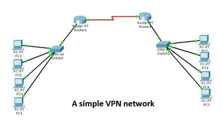
As the first step of configuring a small VPN you can connect two routers as shown in the diagram which is called Back-to-back connection and connect two switches to two Routers and you can connect your PCs to the both switches. As you all know Router a Layer 3 device seperates the broadcast domain. So you have to assign two different network addresses to the both sides.Now lets see the configuration. Since this is your first step we are not going to do any configuration to the switches as we don’t consider any VLAN or other advance options at the moment. In this topic we mainly consider about the router configurations. Here we go…
Router 0:
interface FastEthernet0/0
ip address 192.168.10.254 255.255.255.0
no shut
interface Serial2/0
ip address 10.0.0.1 255.255.255.0
no shut
ip route 192.168.11.0 255.255.255.0 10.0.0.2
copy run start
Router 1:
interface FastEthernet0/0
ip address 192.168.11.254 255.255.255.0
no shut
interface Serial2/0
ip address 10.0.0.2 255.255.255.0
clock rate 64000
ip route 192.168.10.0 255.255.255.0 10.0.0.1
copy run start
Since we use back to back configuration we need to provide the clocking to the DCE interface of the router using clock rate command which you do not need to do in reality as your CSU/DSU provide clocking there.
Then you will have to configure the IPs of the PCs according to the network addresses that we used in router ethernet interfaces and defaulte gateways of that PC should be the IP of the ethernet interface of that router. Here I have shown you only the basic configurations only. Other than this the usual configurations sucha as assignig passwords and descriptions and so on to be done.
Then you need to make sure whether everything is done correctly. Here we do that.
Router#sh ip int brief
Interface IP-Address OK? Method Status Protocol
FastEthernet0/0 192.168.11.254 YES manual up up
Serial2/0 10.0.0.2 YES manual up up
Router#sh ip route
10.0.0.0/24 is subnetted, 1 subnets
C 10.0.0.0 is directly connected, Serial2/0
S 192.168.10.0/24 [1/0] via 10.0.0.1
C 192.168.11.0/24 is directly connected, FastEthernet0/0
As you can see assigning IP and configuration of routing are done. Since we have limited number of networks here we don’t use any routing protocol to configure routing. We will see them later.
Ok then you are done. Try to ping from one side PC to other side PC. You can do it now as we do not block pings here. We will talk about how to block things such as ping and how to firewall the network later.So you can ping right?Have fun.
–Thank you for reading & hope you have got something–
–do not complain if you already know because I can’t help for that–
RED HAT LINUX-Installation & configuration for servers August 29, 2008
Posted by Ravindu Jayalath in Technical.add a comment
 When we talk about open source specially about the Linux OS,the installation and deployments are very important.Proper installation is highly require to maintain an efficient network.Here are some basic steps to follow out the installation.
=>Choose Language-English
=>Keyboard Type-US
<Use prefered installation method>
Disk partitioning layout-Create custom layout(Important)
Disk Partitioning tables
/boot –fstype ext3 –size=100MB -as primary
Volume Group vg00 (LVMv2)
swap –size=8GB(usually 1.5 times RAM)
/ –fstype ext3 -size=4GB
/var –fstype ext3 -size=3GB
/usr –fstype ext3 -size=10GB
/tmp –fstype ext3 -size=2GB
/home –fstype ext3 -size=80GB
Keep rest of the disk space as spare in Volume Group
Use Default GRUB boot loader
No boot loader(GRUB)password-Assuming high physical security
Network
Use static IPv4 and gateway,DNS accordingly
Select Time Zone(for servers better GMT)
Software Installation(As u preffer-do not need much to a server)
Firewall – Disabled
SELinux – Disabled
Make sure ssh is enabled.
–Thank you for reading & hope you have got something–
